4. Working with NUOPC Code
4.1. Create a Fortran Project with Your Model Code
There are two options for creating a Fortran project in Eclipse based on whether the source code you are importing is local or on a remote machine. The simplest approach is to have the source code available locally. However, that is not always practical so Eclipse provides a synchronization capability with files on a remote system accessible via SSH. The sections below describe briefly how to create these two kinds of projects.
See also
This user guide provides only high level guidance in setting up local and remote Fortran projects. More details can be found on the Parallel Tools Platform documentation site.
4.1.1. Projects with Local Files
To create a new Fortran project with local files, right-click (CTRL-click on Mac) on the Project Explorer and select New -> Fortran Project. On the New Project screen you can un-check Use default location and browse to the location of the files. If you use the default location, the project folder will be in the Eclipse workspace folder and you will need to import files manually by selecting File -> Import… from the menu after creating the project.
Under Project type, it is recommended that you select Empty Project under the Makefile project folder. (The project will not actually be empty if you selected the location of your local files.) Click Finish and the new project will be created and will appear in the Project Explorer.
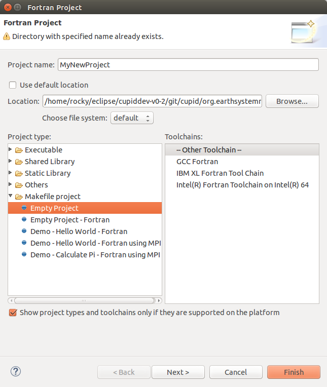
The New Fortran Project wizard.
4.1.2. Synchronized Projects with Remote Files
A synchronized Fortran project will copy files from a remote file system and ensure that the remote and local copies stay synchronized. This is convenient if the code will be built and executed on a remote system. The disadvantage of this approach is that the initial synchronization can take multiple minutes if the size of the source tree is large. However, once the initial synchronization is complete, only changed files need be communicated over the network.
The first step is set up the connection with the remote machine. Open the Connections view by selecting Window -> Show View -> Other. In the list of views, filter for “Connections” and click OK to show the view.
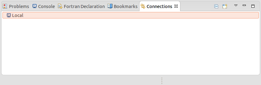
The Connections view.
Create a new connection by clicking the New Connection button (with a small yellow +) in the toolbar on the Connections view. Choose SSH connection on the following screen and click next. On the next screen fill in the details about the connection. The password can be left blank and you will be prompted at each login. In some cases you may need to create multiple connections and use one as the proxy for another, for example, if you must first authenticate through a login node. Click Finish when you are done and you will see the new connection in Connetions view.
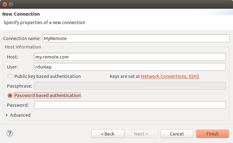
The New Connection wizard.
Now create a new synchronized Fortran project right-click in the Project Explorer and select New -> Synchronized Fortran Project. Fill in the project name, select the remote connection you created and fill in the file path to the root of the source code on the remote system.
You can optionally filter which files are synchronized by clicking Modify file filtering… and choosing certain directories to exclude. In particular, directories containing large data files and other non-source code should be excluded to speed up the synchronization.
Under Project Type select Empty Project under Makefile project. Selecting local and remote toolchains is not required unless you plan to use the Eclipse build system. Click Finish and the new project will appear in the Project Explorer.
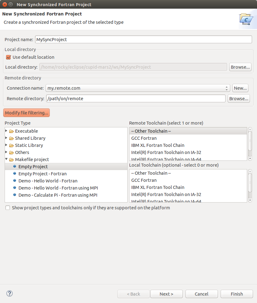
The New Synchronized Fortran Project wizard.
The project will initially be empty and you will need to manually kick off the first synchronization. Do this by clicking the synchronize button in the toolbar or by right-clicking (CTRL-click on mac) the project folder and selecting Synchronize -> Sync Active Now. Remote files will be copied to the local workspace. By default, future synchronizations will happen automatically when changes are made to local files. If the remote files change, or if you notice that changes have not been propagated to the remote system, force a sync using the procedure above.
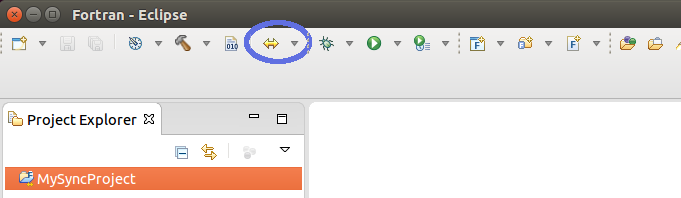
After selecting a project, click the Synchronize button on the toolbar (circled in blue) to kick off the first synchronization. Remote files will be copied to the local workspace.
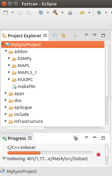
After the synchronization process, files will be visible in the Project Explorer.
4.1.3. Ensure Fortran Analysis is Enabled
Important
Turning on the Fortran analysis/refactoring engine is required for Cupid to work properly.
Cupid depends on the Fortran analysis engine being activated for projects containing NUOPC code. By default it is turned off. To turn it on for a project, right-click (CTRL-click on Mac) on the project folder and select Properties. Under Fortran General -> Analysis/Refactoring check the first box, Enable Fortran analysis/refactoring.
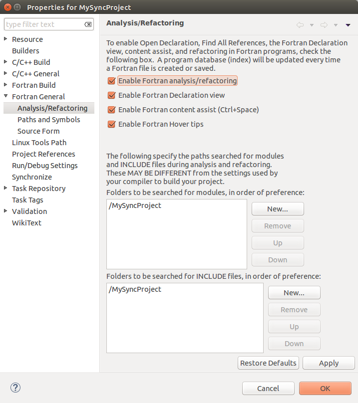
Enable Fortran analysis/refactoring on in the project properties.
4.2. Reverse Engineer a NUOPC Cap
Cupid’s reverse engineering function is capable of analyzing the source code of a NUOPC component to create a representation at a higher level of abstraction. The reverse engineering analysis is limited to only the NUOPC cap of a component, which is typically a single Fortran module. The analysis does not descend into the model code itself. Once the higher level representation is obtained, Cupid is able to provide NUOPC-aware capabilities, such as basic validation of correct API usage and in-place code generation–i.e., weaving new code into the correct places of an existing source file. The reverse engineering analysis phase happens automatically as a background process and an index of NUOPC components in the workspace is maintained.
4.2.1. Show the NUOPC View
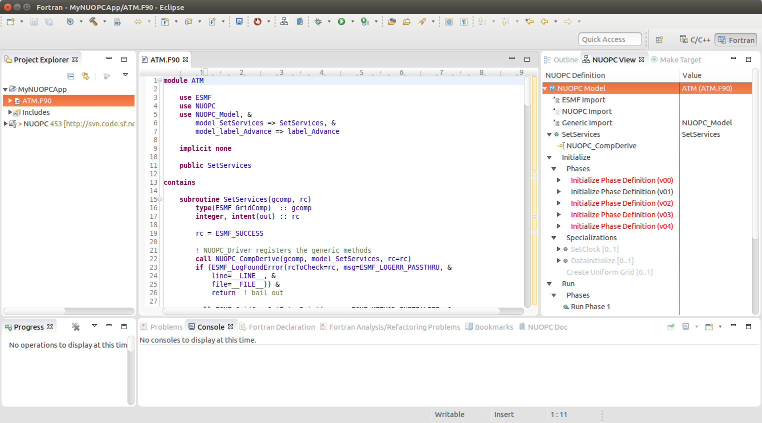
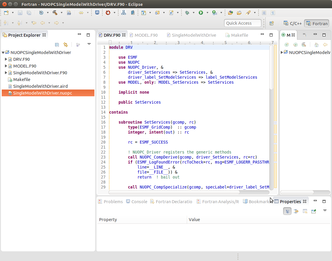
The results of the reverse engineered code can be seen in outline form in the NUOPC View.
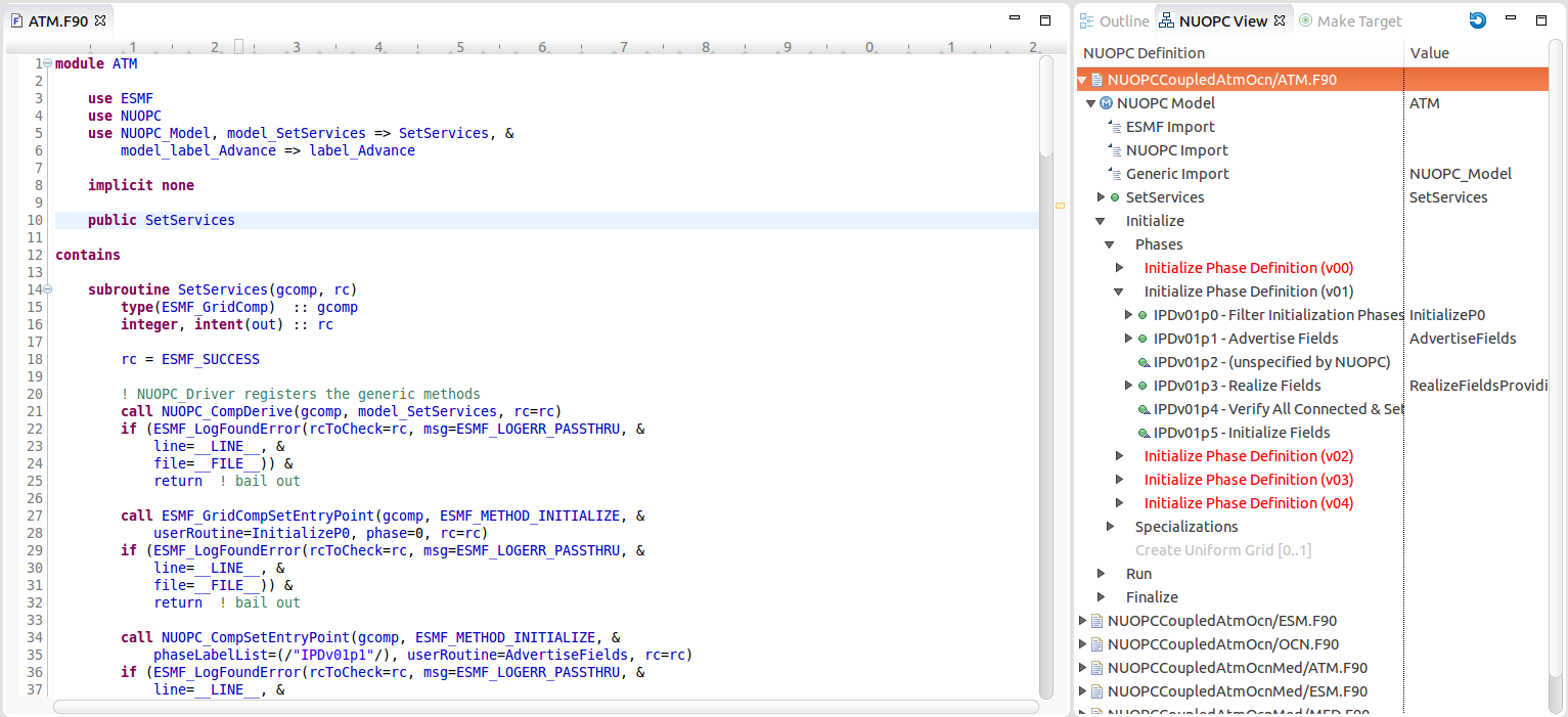
The NUOPC View (to the right of the source code) shows an outline of a reverse engineered NUOPC component.
The NUOPC View is set up to show whenever the Fortran perspective is selected. The current perspective is shown in the upper right-hand corner of Eclipse. There is also an Open Perspective button which can be used to select the Fortran perspective if it is not already shown.
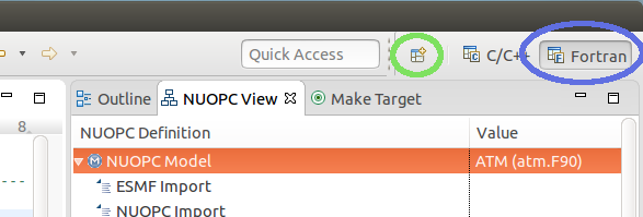
The NUOPC View is set to appear automatically from the Fortran perspective (circled in blue). Click the Open Perspective button (circled in green) to open a new perspective.
There are other ways to show the NUOPC View:
If the NUOPC View is not visible and you open a file with NUOPC code, a dialog will ask you if you would like to open the NUOPC View. This behavior can be turned off in the Cupid preferences (select Window -> Preferences from the menu and select Cupid in the list on the left).
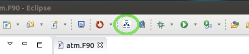
The main toolbar contains a Show NUOPC View button, circled in green below
The NUOPC View can be accessed from the Window -> Show View -> Other menu
The NUOPC View will automatically refresh itself as files are changed and saved in the workspace. It is also possible to force a refresh of the NUOPC View using the refresh button (blue circular arrow) in the top right corner of the NUOPC View. This will first ensure that the Fortran analysis database is up to date and then it will rebuild the index of NUOPC components in the workspace.
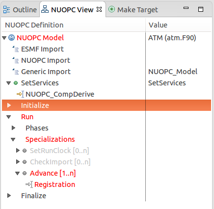
4.2.2. Elements in the NUOPC View outline
The top-level element in the NUOPC View tree are files in the workspace that contain code for a NUOPC component. The first element under each file indicates that type of component (Model, Driver, or Mediator). Sub-elements underneath the component type represent something in the source code, such as a SetServices subroutine, a NUOPC initialization subroutine, a specialization point subroutine, imports of NUOPC generic modules, or calls into the NUOPC API. Many of the elements have small icons: a blue circle with an M maps to a Fortran module, a green circle maps to subroutine, and a yellow arrow pointing to the right represents a subroutine or function call. If a green circle has a small upward triangle in the corner, it indicates that the subroutine is not in the current module, but is inherited from a NUOPC generic component. Grayed out items do not map to any source code element, but represent subroutines or API calls that can be generated. Red items indicate that there is a validation problem rooted at that element. Some elements indicate a cardinality such as [1..n], which indicates that one or more elements of that type can exist, or [0..1], which indicates the element is optional.
The outline is divided into several major sections:
- module imports (only specific ones are shown)
- SetServices
- initialization phases and specialization points
- run phases and specialization points
- finalize phases and specialization points
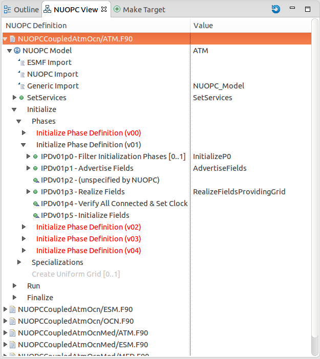
The NUOPC View showing an outline of a NUOPC Model cap.
The NUOPC View is linked to the source code in the active editor. To navigate to the source code related to the element, double-click the element. The relevant code segment will be brought into focus. If the element maps to a subroutine definition, the name of the subroutine will be highlighted. If the element maps to an API call, the call will be highlighted. If an element represents an inherited subroutine (a green circle with small triangle), then it does not appear in the current file, so no code will be highlighted when double-clicking the element.
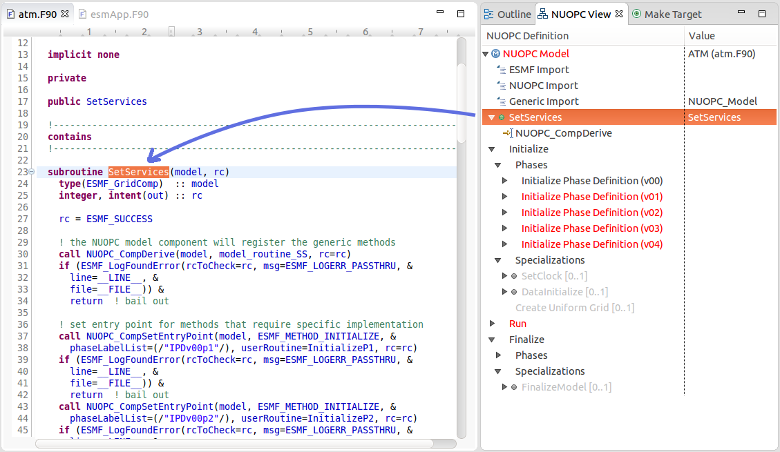
Double-clicking on an element in the NUOPC View outline brings the relevant code segment into focus in the editor.
4.2.3. Validation Errors in the NUOPC View
Elements in red in the NUOPC View indicate a validation error. Currently, the validations performed are to check for missing subroutines and API calls required by NUOPC, e.g., a missing initialization phase or a missing specialization point. The NUOPC Reference Manual details, for each type of component, which subroutines are required and which are optional. Red elements do not indicate a Fortran compilation issue, but indicate that NUOPC expects the element to be present and a runtime error will occur without it. The figure below indicates that the Advance specialization point could not be found during the reverse engineering procedure. Within NUOPC, specialization points are user-provided subroutines that are called by NUOPC. Notice also that parent elements are red all the way to the root of the tree. Therefore, if the root of the tree is red, it indicates a validation issue somewhere below.
To address the issue of the missing Advance element, a new subroutine
needs to be added to the code and that subroutine registered in the
SetServices subroutine. When this is done, the reverse
engineering engine will pick up this code and the red elements
will disappear. The section Generate NUOPC-compliant Code explains how
to use Cupid to generate skeleton code for missing elements.
The Advance element is red because it could not be found by the reverse engineering engine.
Note
Cupid’s reverse engineering and validation engines are based on static source code analysis. The engine depends on an internal program database (Virtual Program Graph or VPG) provided by the Photran plugin for Eclipse.
There are limitations to static analysis giving rise to false negatives–i.e., reporting a validation issue when in fact the NUOPC component will behave correctly. For example, in some cases the reverse engineering engine expects NUOPC API calls to appear within a given subroutine, say SetServices. In reality, the required API call may appear in a different subroutine called by SetServices or even several levels down in the call tree. Cupid does not currently perform a full control flow analysis to find NUOPC calls because it is an expensive operation. And, even control flow analysis is limited due to conditional logic in the code that depends on the state of the program at runtime.
Cupid, therefore, is fundamentally limited by the realities of static analysis. However, most NUOPC caps have a very similar structure with a fair amount of boilerplate code, so we expect that most codes will be correctly reverse engineered.
4.3. Generate NUOPC-compliant Code
Cupid’s code generation facilities make it easier to write the code for a NUOPC cap. A NUOPC cap acts as a kind of translation layer between your model code and the coupling infrastructure. A NUOPC cap is implemented as a Fortran module containing a set of subroutines. Cupid is capable of generating NUOPC Model caps, NUOPC Drivers, and NUOPC Mediators. The code generator can create new Fortran modules for each of these components in new files, or the code generator can insert snippits of code into an existing file after it has been reverse engineered.
There are several options for generating code:
- If there is an existing NUOPC component cap, it should be reverse engineered first as described in Reverse Engineer a NUOPC Cap. Then, using context menus in the NUOPC View, new code can be generated and inserted in-place. This is the right procedure to use, for example, if you need to add an additional specialization point subroutine to an existing cap.
- If there is no existing NUOPC code, a template can be generated for NUOPC Model caps, NUOPC Drivers, and NUOPC Mediators. This is the best option if you have an existing model and need to create a cap so that it can be used in NUOPC-based coupled systems.
- An entire skeleton NUOPC coupled application can be generated, including a main program and Makefile. This is covered in the Generate Skeleton Code for a Complete NUOPC Coupled Application section.
The sections below describe the first two generation options above.
See also
This user guide is not a comprehensive guide to what comprises a NUOPC cap. For a gentle introduction to NUOPC and what is required in a NUOPC cap, please see the Building a NUOPC Model document.
4.3.1. Generate Code In-Place in an Existing NUOPC component
If you need to modify code in an existing NUOPC component (Model cap, Driver, or Mediator), you should first open up the file so that the reverse engineered outline is shown in the NUOPC View. In the following scenario, let’s assume you have an existing NUOPC Model cap for a atmospheric model, but it is missing the required Advance specialization point. This is the subroutine that should call into your model’s run phase to take a time step. In the NUOPC View, right-click (CTRL-click on Mac) on the parent element of the element you would like to generate. The context menu will show you all code generation options currently available.
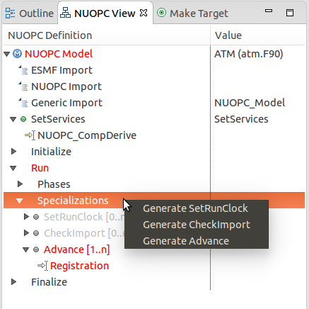
Right-clicking on an element shows a context menu with the available options for code generation.
In the context menu, select the element to generate, in this case
Generate Advance. The requested element will be added to the
outline and the corresponding code generated in the editor. Often, the
addition of one element results in inserting several code fragments.
In the case of the Advance element, a new subroutine is added, a new
import is added to the NUOPC_Model use statement, and a call to
NUOPC_CompSpecialize is added in the SetServices subroutine.
After the code generator runs, yellow markers are added to the vertical bar
to the right of the code editor to indicate where new code was added.
Clicking on one of the markers highlights the generated code.
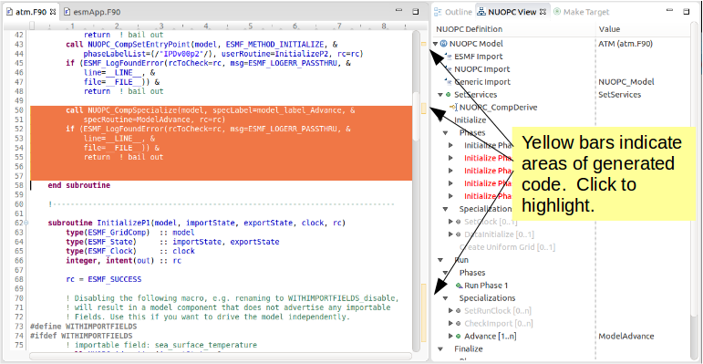
Yellow markers in the vertical bar next to the code editor indicate which code was generated during the last code generation action.
The generated code will compile as is, although it almost always requires additional customization to complete the implementation. In the case of the Advance subroutine just generated, additional code is needed to call into the underlying model’s time step routine. This clearly cannot be generated automatically because it is model-dependent. Therefore a typical workflow will start with a code generation action as just described, followed by filling in any model-specific implementation. This will continue until all required initialization phases are complete and all specialization points have been implemented.
4.3.2. Generate a NUOPC Model cap, NUOPC Driver, or NUOPC Mediator from Scratch
Templates for NUOPC Model caps, NUOPC Drivers, NUOPC Mediators can be generated from scratch. This option is available from the context menu in the Project Explorer. Right-click (CTRL-click on Mac) on a folder in a Fortran project and select New from the context menu and you will see the three options as shown below.
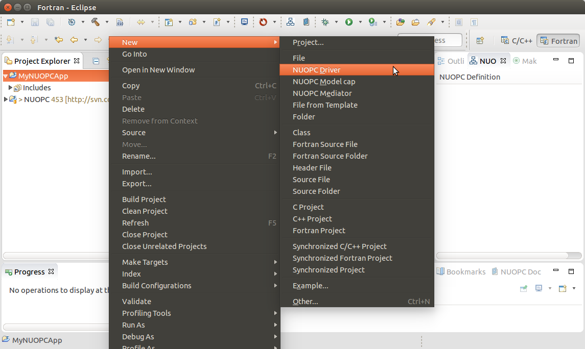
The Project Explorer context menu with options for generating a NUOPC Model cap, a NUOPC Driver, or a NUOPC Mediator.
You will be prompted to enter the name of the component. Click OK and a new Fortran file named <COMPONENT>.F90 will appear in the folder (where <COMPONENT> is the name you provided). The file will also automatically open in the editor and you will see the outline in the NUOPC View. At this point the template can be customized by manually adding code and/or generating code fragments from the NUOPC View outline as described above.
A NUOPC Model cap template.
To compile the code, you will need to modify your model’s existing build system to include the new .F90 file.
4.4. Generate Skeleton Code for a Complete NUOPC Coupled Application
A good way to learn about how NUOPC coupling infrastructure works is to build a skeleton application containing all of the “plumbing” but with no real science code to keep it small.
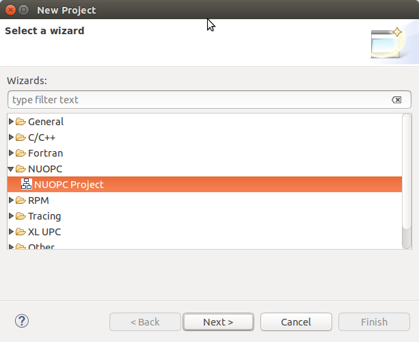
Create a new NUOPC project using the NUOPC Project wizard. Select File -> New -> Project… from the menu. Select the NUOPC Project option under the NUOPC folder and click Next.
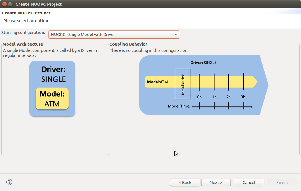
On the next screen, select a starting configuration for the skeleton NUOPC application. Ideally, you should find a configuration that looks something like the actual coupled application you are building.
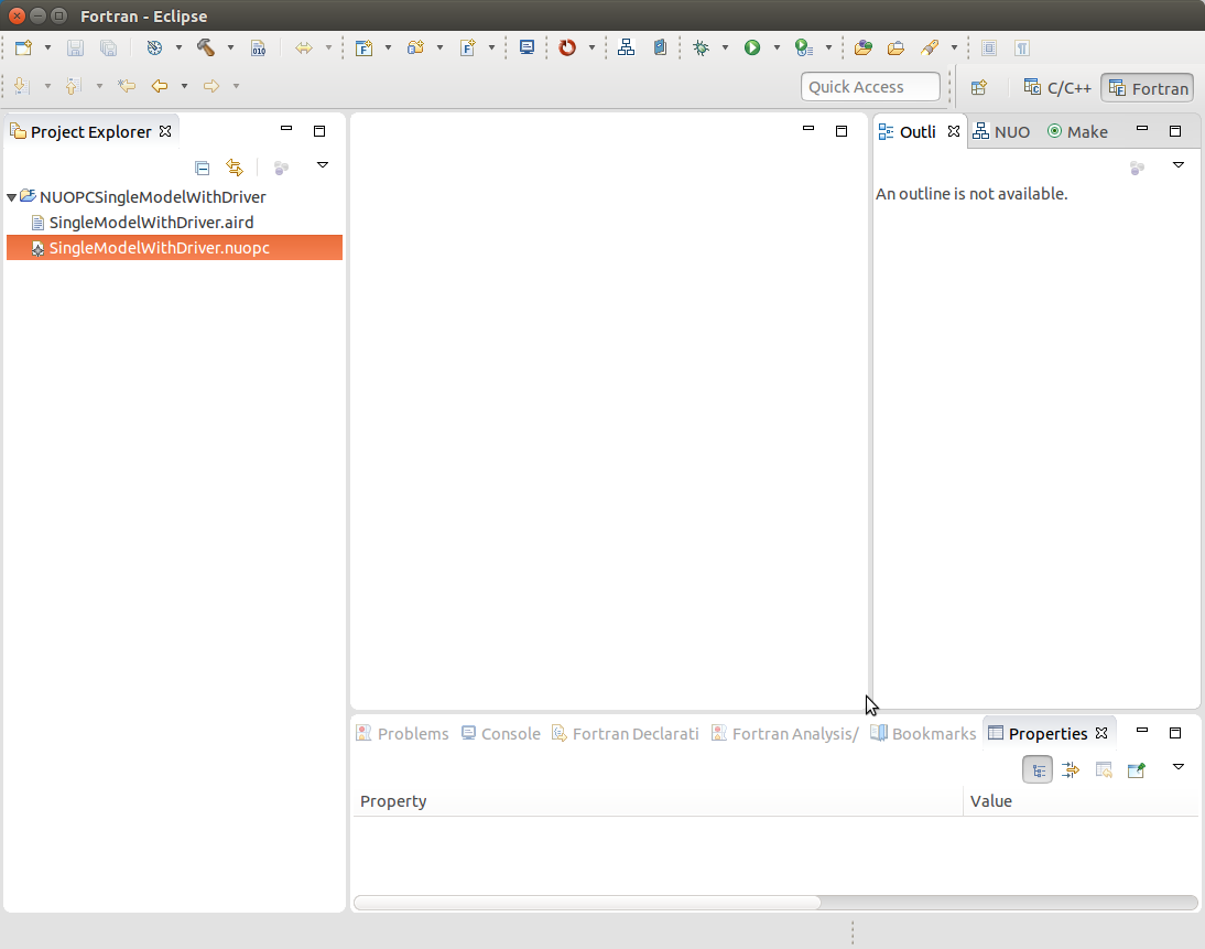
On the final screen of the wizard, type in a project name and click Finish. The new project will be created. Initially, the project will contain a .nuopc file which is a configuration file describing the coupled system.
To generate all the NUOPC code for the system, right-click (CTRL-click on Mac) on the .nuopc file and select NUOPC -> Generate NUOPC code from the context menu. The code for the NUOPC skeleton application will be generated. This includes:
- A NUOPC cap for each Model component
- A NUOPC Mediator, if present in the configuration
- A NUOPC Driver
- A top-level main program
- A makefile
4.4.1. Build the Skeleton Application Locally
The generated code can now be built using make and the generated Makefile. To build on the same system that Eclipse is running (this is the easiest way), first ensure that ESMF v7 is installed.
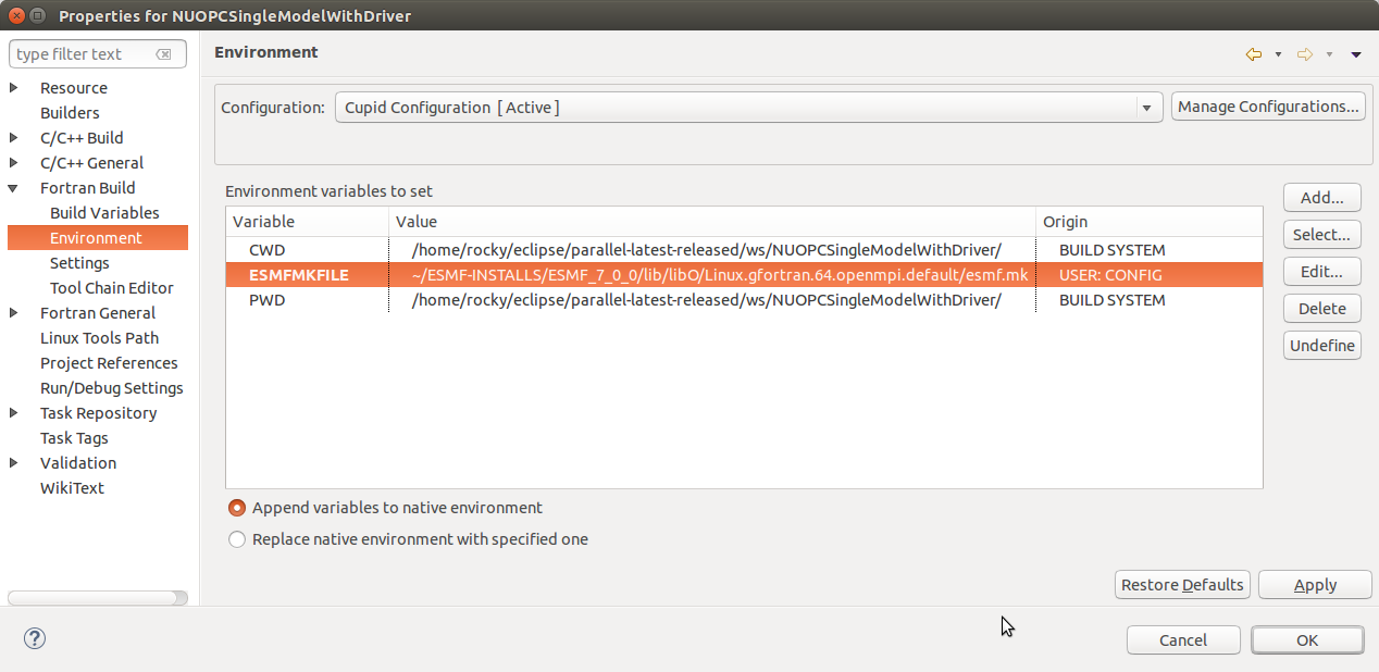
The environment variable ESMFMKFILE needs to be set to the location of the esmf.mk file in the ESMF installation directory. It is in the same directory with the ESMF library file(s). (More info on the esmf.mk file is available in the ESMF User Guide.)
To set the ESMFMKFILE environment variable in Eclipse, right click on the project folder in the Project Explorer and select Properties from the context menu. Select Fortran Build -> Environment in the list on the left and add a new environment variable. Set the name to ESMFMKFILE and the value to the location of the esmf.mk file on your system. Click OK when done.
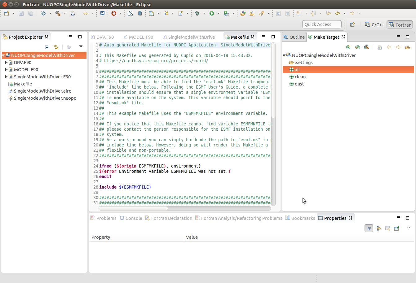
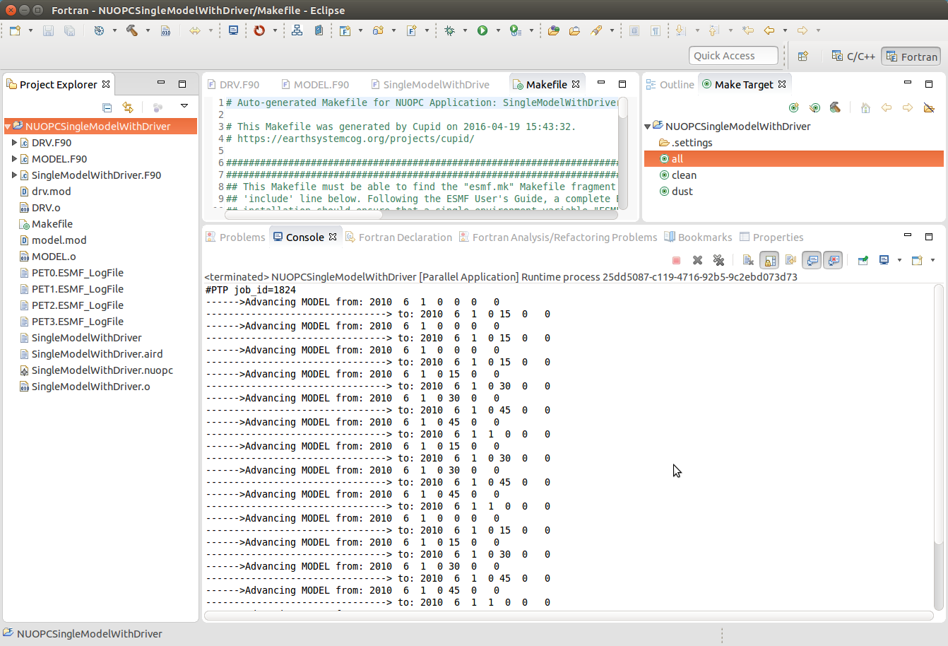
To build from within Eclipse, find the Make Target view on the right side and double click the “all” target. If the Make Target view is not shown, you can bring it up by selecting Window -> Show View -> Make Target from the menu.
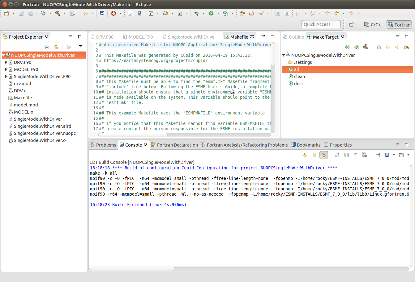
The output from the build will be shown in the Console view at the bottom. The last file built will be the executable and it is typically named the same as the project itself.
4.4.2. Set up a Parallel Application run and Execute Locally
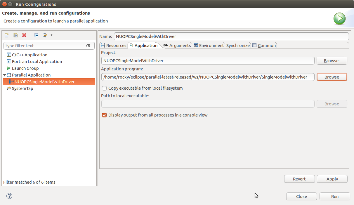
To execute the application on the same system on which Eclipse is running (again, this is the easiest way), set up a Parallel Application run configuration by selecting Run -> Run Configurations… from the menu. The configuration will be dependent on the MPI distribution on your local machine, but you should use the same MPI distribution that was used to compile ESMF. On the Application tab, you need to select the location of the executable that was generated.
After configuring the parallel run, click Run and you will see output from the run in Console. ESMF log files will also be generated, one per process. These are named PETX.ESMF_LogFile. If you do not see the log files immediately after the run, right click on the project folder and select Refresh from the context menu.
4.5. Show the NUOPC Reference Manual
The NUOPC Reference Manual can be shown directly within Eclipse so that you do not need to leave the tool to read API documentation. To open the NUOPC documentation viewer, either click on the Show NUOPC Doc View button in the toolbar or from the menu select Window -> Show View -> Other and select the NUOPC Doc view in the list.
If you select a component in the NUOPC View, the documentation viewer will synchronize with the selected item. For example, if a NUOPC Mediator component is selected in the NUOPC View outline, the documentation viewer will bring that part of the Reference Manual into focus.
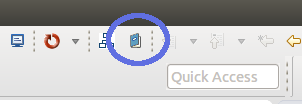
Click the blue book in the toolbar to show the NUOPC Reference Manual.
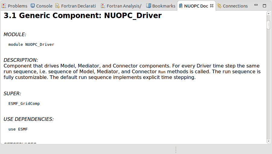
The NUOPC Reference Manual is opened in a small browser built into Eclipse.